Week 16, Assignment 16
Interface and Application Programming
Video - Week Sixteen, Lecture Sixteen
Goal
The Assignment for this week is to "write an Application that Interface with an input or output device that I made, and compare as many tool options as possible". So here I decided to program my "hello world" board for blinking an LED using a designed GUI.
Introduction
Interfacing includes the way for the user to operate the machine and to know vital parameters of the process. Now a days in the world of smart phones applications are becoming the key for everything. Applications are very handy in use and one can easily download the app.
As this week is about writing an application that interface with an Input or Output devices I have made, so I explored through the MIT App Inventor. I used my "Input Devices" board for the assignment. The board has several Pins coming out of the IC Attiny 44 including programming pins, where I can attach any output or input device. I am going to use Arduino IDE for processing or programming my board.
So, to Began with I first went through with some tutorial in YouTube which seemed useful and few tutorials on the MIT App Inventor website which was also very useful. After going through with the tutorials I started with the assignment.
To begin the assignment I decided to use a Servo motor to operate Via an App which I am going to interface using MIT App Inventor.
MIT App Inventor:
As I went to the MIT App Inventor page I first registered there with my e-mail id and soon after that I was able to start working on the interface. Basically MIT App Inventor has two windows, the Designer and Blocks, where the former or maker has to drag and drop the interface and latter looks similar to scratch.
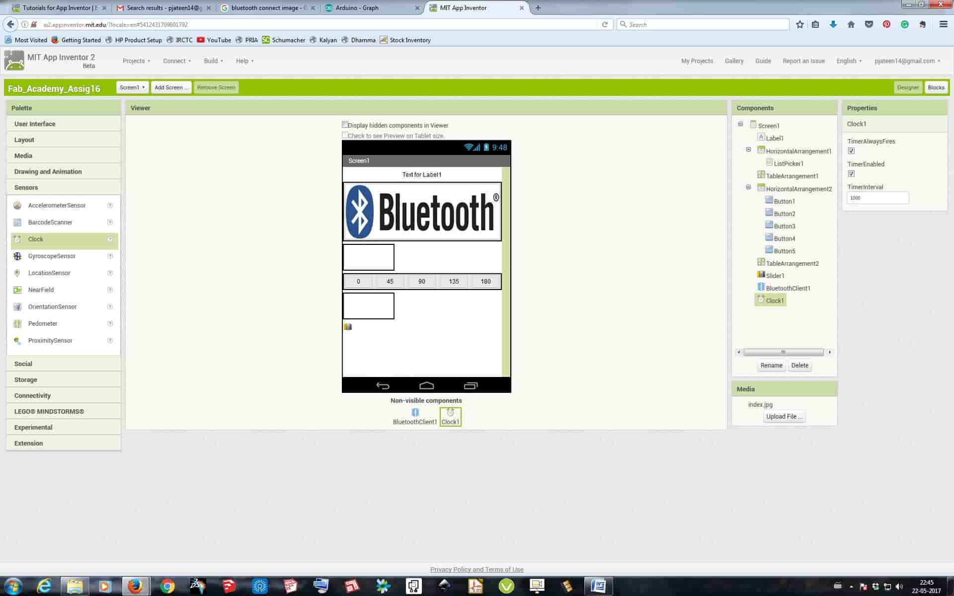
• Designer Window :
Here first I added a layout, and then added a list picker, from the user interface option under palette section, and in its properties gave the width to "Fill Pattern", and then added a Bluetooth image and then again added a Table Layout to maintain the gap between the layouts being placed. I then added 5 different Buttons to the newly added another Horizontal Layout section stating 0-45-90-135-180 inside it, and added another table layout to maintain the gap. Later I then added the "Bluetooth Client" and "Clock" from the Sensors section.
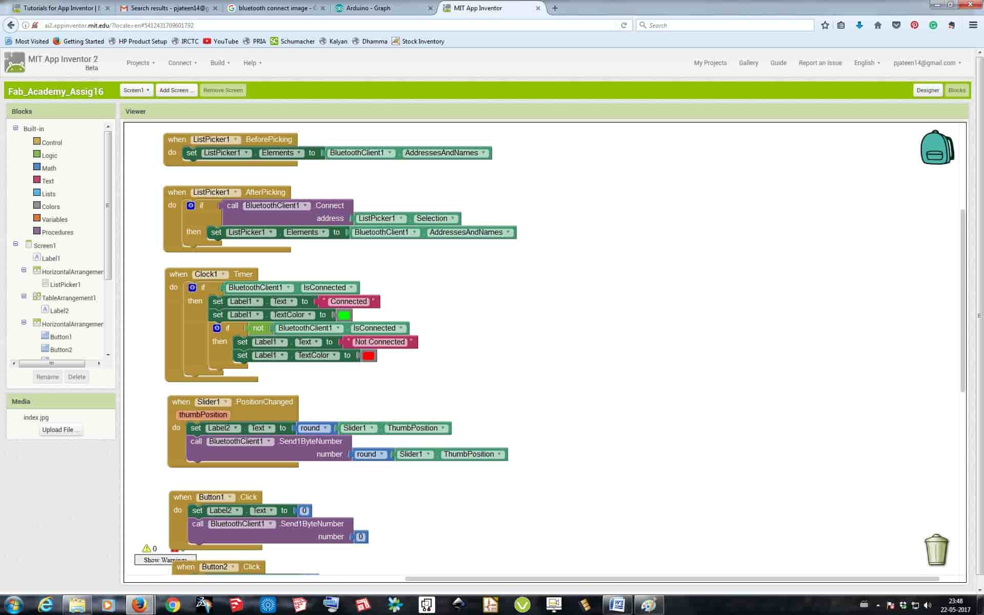
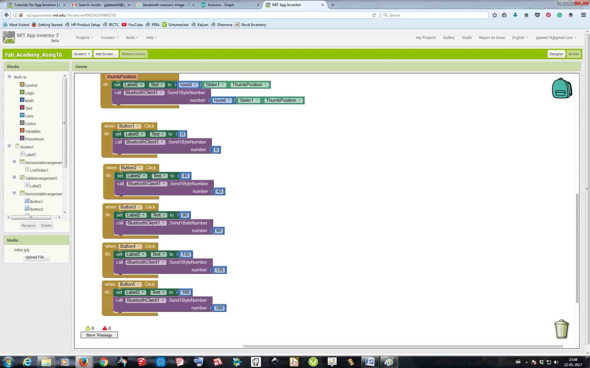
• Blocks Window:
Here I added controls from the list picker to select the Bluetooth devices in the Vicinity and then instructions to show Green color if the Bluetooth is connected and Red color if the Bluetooth is not connected. Then I added 5 different buttons and gave each button a value of 0-45-90-135-180 if pressed.
After all this I came up with something like shown below:
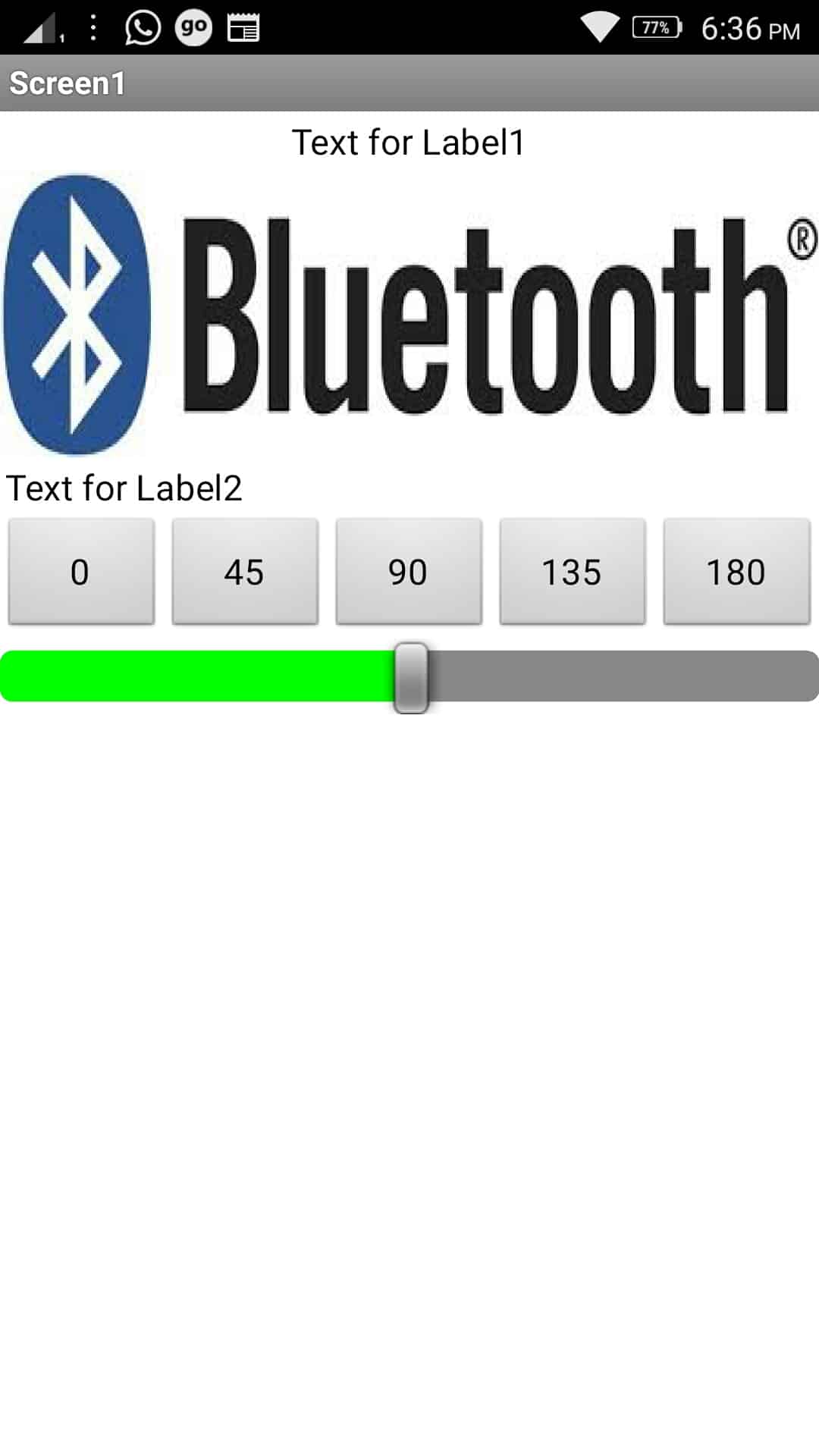
After completing the interface there itself is a option on the top dashboard called "Build" where we can export the interface to an .APK file which can be installed in an android devices. So after doing the same I exported it and installed it in the phone.
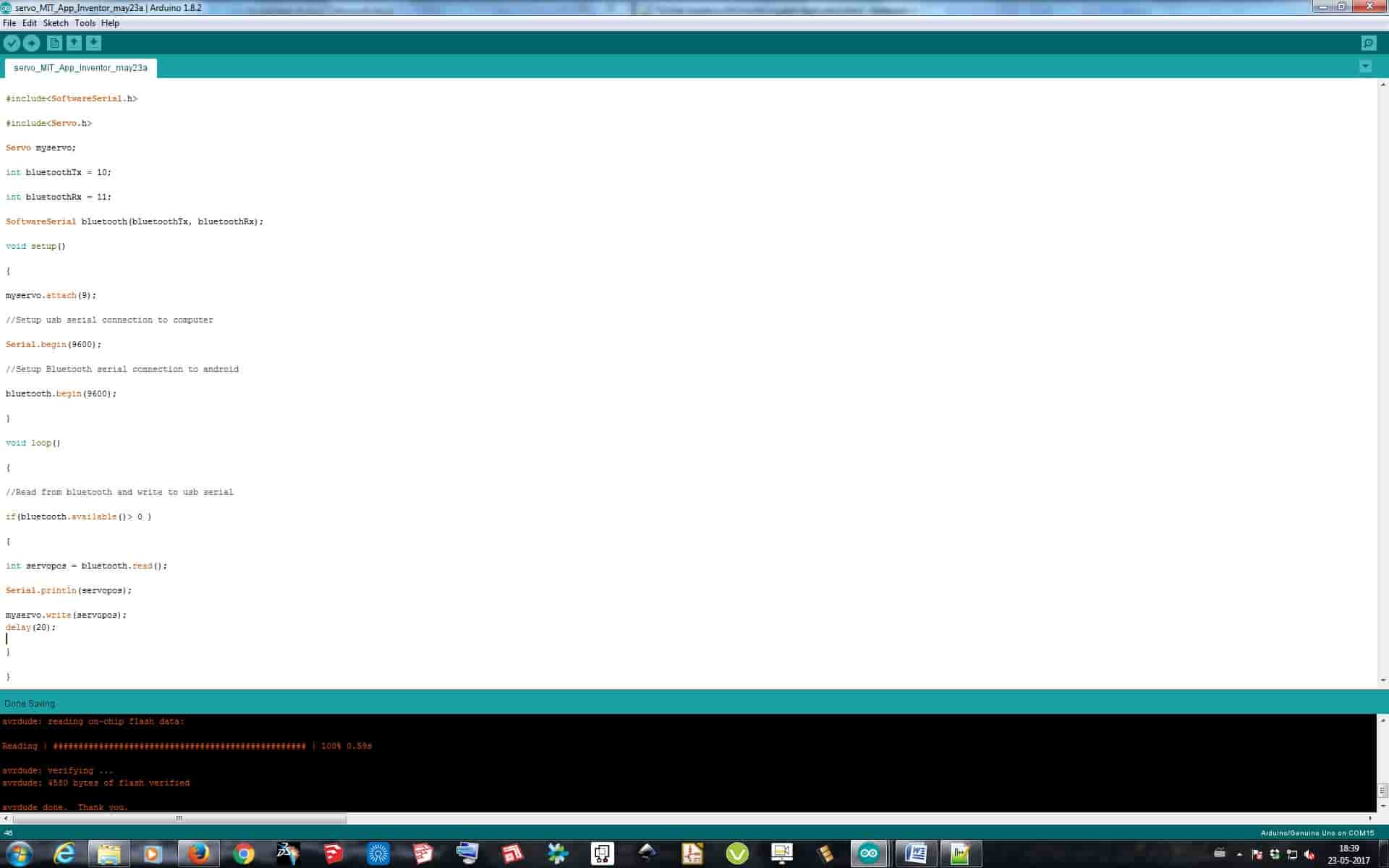
Programming with IDE:
For programming the board I used Arduino IDE, The code which I used is:
#include
#include
Servo myservo;
int bluetoothTx = 10;
int bluetoothRx = 11;
SoftwareSerial bluetooth(bluetoothTx, bluetoothRx);
void setup()
{
myservo.attach(9);
//Setup usb serial connection to computer
Serial.begin(9600);
//Setup Bluetooth serial connection to android
bluetooth.begin(9600);
}
void loop()
{
//Read from bluetooth and write to usb serial
if(bluetooth.available()> 0 )
{
int servopos = bluetooth.read();
Serial.println(servopos);
myservo.write(servopos);
delay(20);
}
}
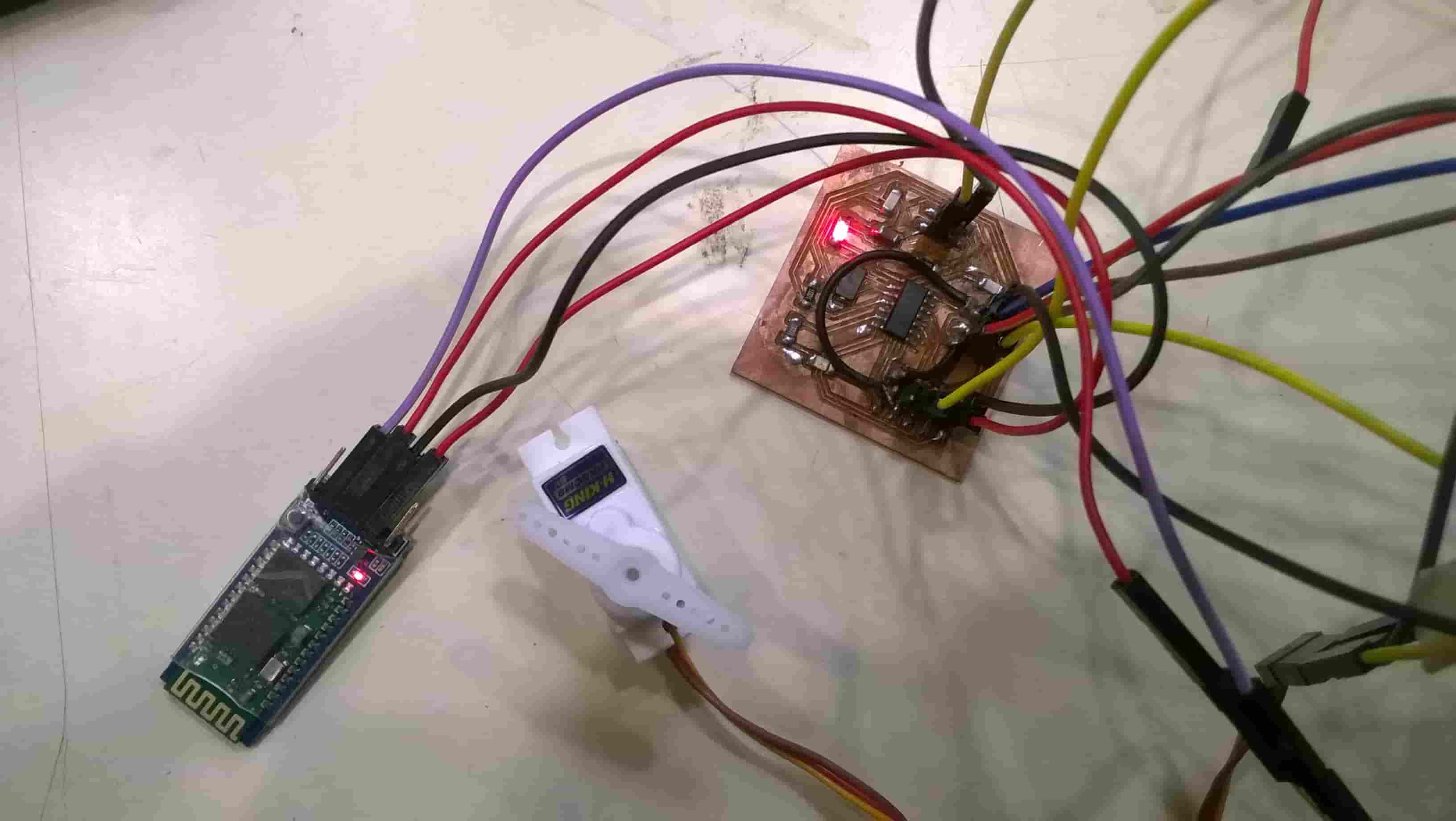
So in the app I first just switch on the Bluetooth of the phone and paired the module with the phone. After connecting in app I just pressed the 5 different buttons of 0-45-90-135-180 and via Bluetooth the motor was getting operated.